CNC routers have gotten complicated with all the kit options and component choices flying around. As a woodworker who appreciates both hand tools and digital fabrication, I’ve spent time understanding what goes into building your own CNC router versus buying one. The build path is genuinely rewarding for the right person. Today, I’ll share everything I know about building a CNC router from scratch.
How to Build Your Own CNC Router
Building a CNC router may seem overwhelming at first. But with the right knowledge, the right components, and a methodical approach, constructing your own machine is achievable — and it teaches you more about how the tool actually works than buying a finished unit ever will.

What a CNC Router Does
A CNC (Computer Numerical Control) router translates computer commands into precise physical movements, directing a rotating cutting tool across wood, metal, plastic, or other materials. The precision achievable through CNC work goes well beyond what’s practical by hand — which is exactly why the technology has become accessible to small shops and serious hobbyists, not just industrial facilities.
The Core Components
A functional CNC router requires six main components, each with a specific role:
- Frame: The structural foundation. It houses and supports everything else. Rigidity is the most important characteristic — any flex in the frame translates directly into inaccurate cuts.
- Linear motion parts: Rails, carriages, and bearings that enable movement along the X, Y, and Z axes. Precision in the linear motion system determines the machine’s overall accuracy.
- Lead screws: Convert rotational movement from the stepper motors into linear movement along each axis. The pitch of the lead screw determines how far the machine moves per motor rotation, which directly affects resolution.
- Spindle: The cutting tool — the business end of the machine. Spindle selection should match your expected material and depth of cut. A light Dremel-style spindle suits engraving and fine work; a full router spindle handles deeper passes in hardwood.
- Electronics: Stepper motors, driver boards, power supply, and the computer interface that connects your machine to your design software. These are the machine’s nervous system.
- Software: CAD (Computer Aided Design) creates your design; CAM (Computer Aided Manufacturing) converts it to G-code the machine reads. Several software options exist at various complexity levels and price points.
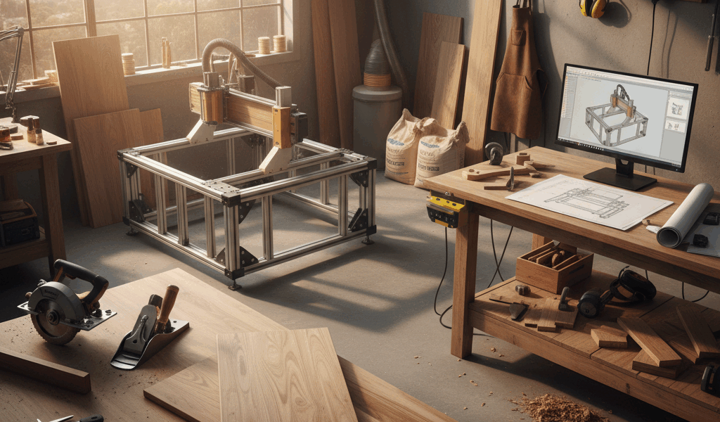
Planning and Design
Start by sketching the machine’s basic configuration. Define the cutting area you need — this determines the machine’s physical footprint. I’m apparently a “design for the largest project I’ll ever run” person and building a bigger cutting envelope always works better for me while building too small always means I wish I’d planned differently. Factor in your workspace dimensions and what you realistically plan to cut.
Building the Frame
Frame material choice comes down to budget and priorities. Steel offers maximum rigidity and durability but is heavy and requires welding or bolted fabrication. Aluminum is lighter and easier to work with, accepting standard machined hardware. Whatever material you choose, the frame must be square and rigid — any flex introduces error that no amount of software calibration can fully correct.
After the frame, install linear rails and bearings. These allow the gantry and Z-axis to move smoothly and repeatably. Precision here matters more than anywhere else in the build. Take the time to align everything carefully before moving on.
Selecting the Spindle
The spindle choice shapes the machine’s capability. Match spindle size and power to your expected workload. The frame must handle the spindle’s weight and the vibrations it generates during cutting — oversizing the spindle on a light frame causes problems. For woodworking applications, a 1-1/4 HP to 2 HP router mounted in a spindle holder is a common and practical choice.
Electronics and Control
Stepper motors drive the lead screws on each axis. Size the motors for your machine’s mass and expected cutting forces — too small and they’ll skip steps under load; too large and you’re spending money on capacity you don’t need. Driver boards control the motors, receiving instructions from the computer and converting them into precise step signals. Several beginner-friendly driver board options are available at accessible price points.
Power supply sizing should match the motor and driver board specifications exactly. A USB or parallel port computer interface connects the machine to the CAD/CAM software running on a dedicated computer.
Software Setup
Once the hardware is assembled and wired, the software brings it to life. Verify motor direction and calibrate axis movement before cutting anything. Set up your CAD software for design work and your CAM software to generate G-code. Run a simple test cut — a square or a circle — to verify that the machine is producing accurate geometry. Minor calibration adjustments at this stage prevent larger problems later.
One Final Thought
Building a CNC router is a project that teaches you far more than using one does. Every component decision, every alignment challenge, and every calibration step builds your understanding of how the machine works — which makes you a better operator of any CNC tool going forward. That’s what makes the build path endearing for woodworkers with a technical curiosity: the machine becomes something you understand deeply, not just a tool you operate.